Model Airplane Engine Installation
Installing the model airplane engine is probably my favorite part of the build. It won't be long now before we get this bird in the air!
First you'll need to decide whether to mount your engine upside down, right side up, or sideways. You always want to coat your firewall with some sort of fire resistant coating. After deciding on a engine mount, you'll need to verify the thrust angle, install the fuel take and throttle linkages.
The final step is to trim the cowling so that it not only looks good, but allows for enough cooling air and easy access to the fuel adjustment needles.
Orientation of Engine
Your engine can be installed upright, inverted, sideways, or anywhere in between. Mounting upright is always the best choice if possible. If your airplane does not have an engine cowling this is how you should mount it.
Mounting the engine upright gives you easy access to the fuel adjustment needles and makes it very easy apply the glow ignitor for starting.
Engines mounted upright tend to start easier due to the position of the carburetor in relation to the fuel mounted in your radio controlled airplane.
If your model airplane engine has a cowling it may not be possible to mount the engine upright. A sideways mounted engine is better than an inverted engine if you have the choice.
Engines mounted inverted can be difficult to start and may have trouble idling, so this should be the last option.
Engine Mounts
Some of the older radio control airplanes have wooden engine mounts built into the airplanes structure. This makes for much for difficult repairs after a rough landing.
Just about all airplanes nowadays have a thick firewall where a removable engine mount is attached. The model airplane engine bolts directly to the mount.
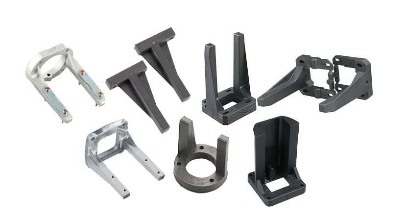
There are several types of RC airplane engine mounts to choose from. They can be either aluminum or fiberglass filled nylon. Some are two-piece designs, some are adjustable, and some have clamps to hold the engine in place.
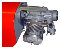
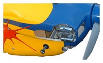
If you look closely you can see that the engine in the above picture is mounted with a clamp mount. Some mounts (like the aluminum one in the above picture) are pre-drilled to fit certain engines. ARFs and most kits come with an engine mount for you to use.
Fire Proofing Your Airplane
The firewall of a glow powered RC airplane is constantly being doused by un-burned fuel from the engine. This will literally cause the firewall to rot away very quickly if not protected.

The firewall is what transmits all of the thrust from the engine to the airplane. The last thing you want happening is the firewall busting in half in mid flight
Fireproofing the firewall is very simply. Just put a good coat of epoxy glue over the entire surface and your good to go.
A company called Klasskote makes a product that is perfect for this application.
Thrust Angle of an RC airplane
Just about all model airplanes engines are mounted to produce a little bit of down and right thrust. This just means that the engine is pointed downward and to the right. Changing this thrust angle changes the flight characteristics of the airplane.
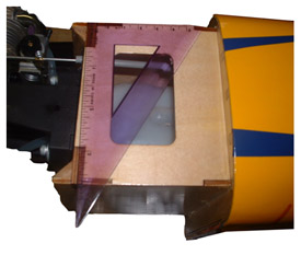
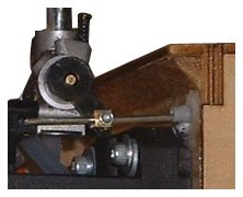
The picture above is a birds-eye view of the firewall on my Great Planes Cap 580. You can see by looking at the "square" that there is a tiny bit of right thrust built into the firewall.
The position of the engine mount on the firewall must be positioned slightly up and to the left of the geometrical center to compensate for the thrust angle. This is done to insure that so that the actual thrust of the propeller is centered on the firewall.
If you are putting together an ARF or building a kit, the model will have this thrust angle built into the firewall for you.
Unless you are building an airplane from scratch, you dont need to be an aeronautical engineer to mount the engine! Just follow the directions that came with the airplane and everything will be just fine.
Mounting the Model Airplane Engine
You will need to determine how far forward or backward the engine should be mounted on the engine mount. The instructions will tell you exactly where the back plate of the spinner needs to be in relation to the firewall.
I usually install the engine mount to the firewall first. Then I set the engine on the mount and position it so that the back plate of the spinner is in the correct location indicated by the directions.
I use just a touch of CA glue to hold the engine in place. Then I mark the holes in the mount with a sharp object such as a nail. I also scribe the mount around the feet of the engine mounting tabs.
The engine should not be squeezed tightly between the two mounting bars. The only portion of the engine that should be touching the mount is the mounting tabs where the engine is actually bolted to the mount.
You also need to make sure the engine sits nice and flat on the mounting bars. If the mounting bars are uneven they will become twisted when you tighten the bolts, and that spells trouble because this could throw off the thrust angle or crack the mount.
After you have carefully marked where the holes should be on the mount, remove the mount from the firewall. It is best to use a drill press to drill these holes.
If you dont have a drill press you can put the mount in a vice and use a standard hand drill (thats what I do). But you must be very carefully to drill the hole straight down. Drilling the hole at an angle will put stress on the engine mount and mounting bolts.
Once the holes are drilled simply bolt the engine mount to the firewall, and bolt the engine to the mount. Your model airplane engine is now mounted!
Fuel Tank Installation
Kits and ARFs either come with a fuel tank or will recommend what size the fuel tank should be. A larger fuel tank will obviously allow you to fly your radio controlled plane longer before running out of fuel. You can go slightly larger than the recommended size. But dont over do it!
The center-line of the fuel tank should be about the same level as the high speed needle valve if using a glow engine. The way that a glow engine draws the air/fuel mixture into the engine is very touchy.
The tank elevation isn't really that critical when using an RC Gas engine with a fuel pump.
If the tank is too large it will throw this balance off and the engine may not run consistently when diving or climbing.
Also keep in mind that the larger the tank is, the more the center of gravity of the airplane will change as the fuel is burned. It is best to use the size tank that is recommended in the directions. But it doesnt hurt to use a slightly larger or smaller tank.
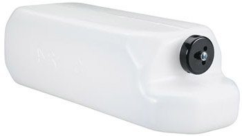
A typical model airplane engine's fuel tank has two pieces of aluminum tubing that fits through a rubber stopper in the opening of the tank. When the back-plate of the stopper is tightened, the stopper seals around the tubing and opening of the tank. One piece of tubing is a vent line and the other is the fuel suction line.
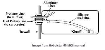
The vent line is bent upwards towards the top of the tank. The line is hooked to the nipple on the exhaust muffler. This pressurizes the tank helping the engine to pull the fuel from the tank. It is bent upward to minimize the formation of unwanted air bubbles from forming in the tank. Glow engines don't like air bubbles!
The other tube, the suction line, extends in to the tank a short distance and stops. A fuel line is connected to this tubing. A fuel clunk is attached to the other end of the tubing.
The tubing length should be sized so that the clunk is as close to the bottom of the tank as possible and swings freely back and forth without getting hung up when the tank is held vertically. The clunk acts as a weight so the suction line is always submerged in the fuel whether flying inverted or right side up.
It is normal procedure to remove the fuel suction line from the carburetor to use your fuel pump to fill or empty the tank. If you have a cowling over your engine you surely don't want to remove the entire cowling every time you fill or drain the tank.
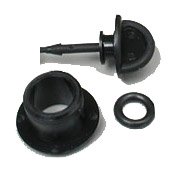
Add a second fuel suction line for filling and draining the tank. A fuel dot can be installed in the cowling for the fill line.
When all the fuel lines have been installed into the tank you will need to check it for leaks. You can pinch one line and blow into the other line while the tank is submerged in water and check for bubbles. This is an important step because a tiny leak will not only cause your radio controlled airplane to rot away, it will also cause the engine not to run correctly.
The tank should be wrapped in foam before installing it into the airplane. You can use rubber bands or tape to hold the foam in place during the fuel tank installation. The gas tank compartment of the airplane should also be filled with foam. This helps to prevent the formation of air bubbles due to vibrations from the engine.
First, hook the airlines to the tank. Position the airplane nose down and with the help of gravity you can thread the tubing through the hole in the firewall. Then pull the tubing through from the other end while pushing the fuel tank forward until the tank is in position.
Glue a piece of balsa across the back of the fuel tank department. Add enough foam until the tank is supported firmly in all directions.
When filling the tank, you attach your fuel pump to the line that is normally hooked to the high speed needle valve. Pull the vent line from the exhaust nipple. Fill the tank until fuel begins coming out of the vent line.
If you have an engine cowling and the vent line on the exhaust is not easily accessible, you then fill the tank through the fuel dot connected to the second suction valve you added.
When fuel begins to come out of the exhaust you know the tank is full. I always keep a small plastic container to catch the over flow. Money doesn't grow on trees!
Engine Throttle Linkage
Once the fuel tank is in place and the model airplane engine is mounted, it is time to connect the throttle arm of the carburetor to the throttle servo.
Because the fuel tank is generally in the way, a flexible cable-type pus-hrod is sometimes used for this. If the fuel tank is not in the way then an aluminum push-rod in a nylon tube can be used. Again,the directions should show you exactly where to route the push rod and what type to use.
It is very important that the cable or rod slides inside the tube freely with no resistance. It is also important that the outer tube is supported firmly the entire route.
When using a flexible cable-type pushrod, determining the correct length for the throttle cable can be tricky. If you are using an aluminum push rod you can get the length in the ballpark and use an E/Z connector for the final adjustment as can be seen in the above picture.
When using a flexible cable you will have to cut the cable to the correct length. You will also have to solder an adjustable connector to the throttle side of the cable and solder a servo connector to other end of the cable.
The first step is to solder the servo connector to the cable. With the radio on and the throttle in the neutral position with the trims centered, the servo arm should be be perpendicular (90 degrees) to the path of the cable.
Adjust the connector on the throttle end of the cable so that there is equal adjustment left in both directions, then attach it to the throttle arm (the connector is not soldered to the cable at this point). Move the throttle arm on the engine's carburetor until the hole in the throttle barrel is just barely open.
Move the throttle stick on the transmitter to fully closed, with the trim centered. Pull the cable tight between the servo arm and carburetor arm and mark the location where the cable meets the throttle connector. Cut the cable at this mark. The final step is to solder the adjustable throttle connector in place and attach to the throttle.
This needs to be a fairly accurate measurement. You can be off slightly because you have the adjustable connector on the end of the cable along with the radio trims to allow for some adjustment. If you measure too long you can simply cut cable short and solder on a new connector. If you measure to short you will have to replace the entire cable. So its better to err on the side of being a bit to long.
Model Airplane Engine Cowling
If your model airplane engine has a cowling, you will need to customize it to fit your engine. You will have to make the glow plugs as well as the carburetor adjustment needles accessible. You will have to cut a hole for the exhaust.
Since the model airplane engine is partially air-cooled, you will have to cut holes in the front of the cowling for air ventilation. A portion of the underside of the cowling must be open to allow the air to exit the cowling.
Adding a fuel dot for filling and draining the engine is also needed.
Customizing the cowling to fit your model airplane engine is a very tedious process. You start by marking on the cowling where the exhaust and engine head would protrude.
First cut small holed and slowly keep enlarging the holes a little bit at a time until every thing fits just right. Dont get in a hurry. It's kind of like cutting hair. You can always trim a little more, but you cant put it back!
Many times it is necessary to install an exhaust deflector to route the exhaust out of the cowling and away from the airplane. You want to avoid having the inside of your cowling filled with unburned oil from the engine.It looks bad and is hard to clean up.
You can get rubber or steel exhaust deflectors. I kind of like the rubber ones better. Thats probably because all of the metals ones Ive installed are lying at the flying field some place.
You may like these pages as well...
- How to Fly RC Airplanes Successfully
- RC Airplane Controls
- First Flight Walkthrough
- Model Airplane Accessories
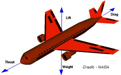
- How Airplanes Fly
Home > Nitro RC Engines > Model Airplane Engine Installation
Let’s Go Flying! |
|
5 Steps for Successful First Flight! When the RC bug bites, it bites hard! Control yourself my friend! Save yourself much time and money by following these five steps to success! |

|
Follow us on: |
|