Your Basic Servo Tutorial
Here's an easy to read explanation of how servos REALLY work. This servo tutorial will focus on the concept of Pulse Position Modulation (PPM), which is the radio language that all receivers use to communicate with servos.
Did you know that PCM receivers translate the PCM signal from the transmitter to the PPM language for the servo to understand?
How Servos Work
A servo consists of a small DC motor, small set of gears, a potentiometer, and electronics for controlling feedback.
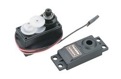
Each servo has three wires. A series of relatively low voltage control pulses are sent to the servo from the receiver through the white wire. The black and red wires provide the electrical power needed to operate the DC motor.
A servo receives the command or pulse from the receiver every 20ms. The servo must hold that position for the next 20ms until it gets the next pulse. The servo must hold this position even if the forces from the control surface are trying to make it move.
Have you ever tried to move the elevator of your airplane with the radio on and with the sticks in the neutral position? If you so, you've probably noticed that the servo will fight you to keep the elevator in neutral position. Never tried it? Well, that's your homework for this servo tutorial!
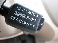
Are you wondering how it does this? It does it exactly the same way cruise control maintains the same speed going up hill or down hill. Both servos and cruise control use feedback.
With cruise control, the speedometer provides the feedback. The electronic circuitry looks at the speedometer and compares it to the set speed. If the value of the speedometer is greater than the set speed, the circuitry sends a signal to let off the gas pedal. If the value of the speedometer is less than the set speed, the circuitry sends a signal to give more gas. Since it does this several times a second, it is so smooth you don’t even notice it.
Instead of a speedometer, a servo uses a potentiometer (pot) for feedback. The potentiometer is a resistor that changes resistance as it rotates. It is mechanically coupled to the servo's motor and gears so it rotates with the servo motor.
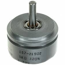 Servo Potentiometer |
The circuitry in the servo knows the exact position of the servo from looking at the voltage coming from the pot (resistance goes up, voltage goes down). The circuitry compares the position dictated by the receiver with the position indicated by the pot. The circuitry then tells the servo motor to move in the appropriate direction to minimize the difference. |
Pulse Position Modulation
The most important thing to remember from this servo tutorial is that all standard servos use the Pulse Position Modulation (PPM) language.
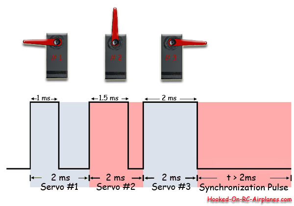
A pulse is simply whether or not the control voltage is on or off. The amount of time that a pulse is on during a 2ms time frame dictates the servos position. This time frame, or sequence, repeats around 50 times per second.
During the first half of this 2ms time frame, the pulse is always on. This starts a counter, so to speak, to tell the servo to start listening for the command. The second portion of this 2ms time frame is the command that dictates the position of the servo.
Take a look at the chart below to help you better understand this servo tutorial. The amount of time during the designated 2ms time frame that the pulse will be on for the three most extreme positions(far left, far right, neutral). There are an infinite amount of positions in between these values and amount of time the pulse is ON changes in proportion. This infinite nature of possibilites is what makes pulse position modulation analogue instead of digital.
Servo #1:
Far Left Command: Time ON = 1 + 0.0 ms = 1.0 ms
Servo #2:
Neutral Command: Time ON = 1 + 0.5 ms = 1.5 ms
Servo #3:
Far Right Command: Time ON = 1 + 1.0 ms= 2.0 ms
PCM vs PPM
The purpose of this servo tutorial was to give you a very basic understanding of how a servo works. Check out the RC Servo Page for more information servo specifications and help with choosing the right servos for your RC airplane.
While PPM is the only language a servo knows, it is not the only language used by transmitters and receivers. Pulse Code Modulation is digital type of radio language used in our hobby. A PCM receiver translates the PCM language to PPM language so the servo will understand. Find out the pros and cons of PCM vs. PPM radio systems.
Related Pages
Home > RC Airplane Radio Systems > Servo Tutorial
Let’s Go Flying! |
|
5 Steps for Successful First Flight! When the RC bug bites, it bites hard! Control yourself my friend! Save yourself much time and money by following these five steps to success! |


|
Follow us on: |
|
|